

RC G1 Tactile Glove — Data Protocol & Pairing Reference
Binary frame format, AT command set, LED state table, and troubleshooting for the RC G1 Tactile Glove serial / Bluetooth protocols.
Use this page when you’re writing your own reader or integrating the G1 into a custom data pipeline. It covers the binary frame format, the AT command set on the serial channel, every LED state, and the most common failure modes. If you only need to plug in and record, start with the Windows, macOS, or Linux setup pages.
Reference Updated May 2026 Difficulty: Advanced
1. Hardware Architecture
A G1 deployment has five components. Only the first four are required for a single-glove rig; the USB hub is for multi-glove (LH + RH) setups.
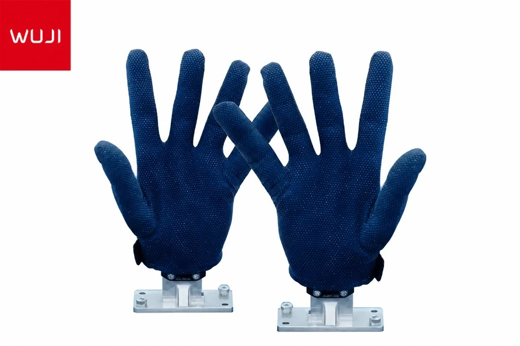
- Fabric sensor array. 162 piezoresistive sensing points arranged on a 16×16 logical matrix (256 ADC slots, of which 162 are physically wired to sensors; the unwired slots read near zero and can be masked in software).
- Data-acquisition module (A-board). ESP32-based Bluetooth MCU with an integrated 300 mAh / 3.7 V battery, USB-C for charge / data / firmware, a hardware tactile button, and a status LED. 50 × 32 × 15.5 mm; 6.6 g board + ~15 g battery.
- Bluetooth USB receiver (dongle). 1:1 paired with a single A-board. USB-A, 66.1 × 23.2 × 13 mm. Optional — cable-only operation is fully supported.
- USB 3.0-to-Type-C cable (2 m). Serial connection at 921 600 bps default, optional 3 000 000 bps high-speed mode.
- USB hub. For multi-glove rigs (e.g. bimanual LH + RH).
Data flow:
  +--------------------+     +--------------------+        +--------+
  |  Fabric sensors    | --> |  A-board ADC       | --+--> | Host   |
  |  (162 / 16x16)     |     |  (ESP32 + IMU)     |   |    |        |
  +--------------------+     +--------------------+   |    +--------+
                                       |              |
                                       | BLE 30 Hz    | USB-C 100 Hz
                                       v              | (921600 / 3M)
                              +--------------------+  |
                              |  BT USB dongle     | -+
                              |  (CH340 endpoint)  |
                              +--------------------+
2. Serial Configuration
- Default port settings: 921 600 baud, 8N1, no flow control.
- Optional high-speed mode: 3 000 000 baud — requires a firmware-side config change, contact support.
- USB chip on both the data-acquisition module (when wired) and the Bluetooth dongle: CH340 (WCH USB ID
1a86:7523). - Linux: in-tree kernel driver
ch341. macOS: installCH34xVCPDriver.app. Windows: installCH341SER.EXE.
The same binary protocol described in §3 works on either the wired or the BT-dongle serial path — you should not need to special-case the transport in your reader.
3. Binary Frame Format
A complete sensor reading is delivered as two packets that together carry 256 pressure values plus 16 bytes of IMU data. Each packet begins with the constant 4-byte sync header AA 55 03 99, followed by a 1-byte sequence number (0x01 or 0x02) and a 1-byte sensor-type ID.
Byte layout for one sensor pair (packet 1 + packet 2)
| Offset | Length | Field | Description |
|---|---|---|---|
| Packet 1 (sequence = 0x01) — 134 bytes total | |||
0–3 |
4 B | Sync header | Constant AA 55 03 99 |
4 |
1 B | Sequence | 0x01 = first half |
5 |
1 B | Sensor type | 0x01 LH, 0x02 RH, 0x03 LF, 0x04 RF, 0x05 WB |
6–133 |
128 B | Pressure payload A | First 128 of 256 raw pressure values, 8-bit unsigned ADC (0–255) |
| Packet 2 (sequence = 0x02) — 150 bytes total | |||
0–3 |
4 B | Sync header | Constant AA 55 03 99 |
4 |
1 B | Sequence | 0x02 = second half |
5 |
1 B | Sensor type | Same value as packet 1 |
6–133 |
128 B | Pressure payload B | Last 128 of 256 raw pressure values |
134–149 |
16 B | IMU quaternion | 4 little-endian IEEE-754 floats: w, x, y, z |
Sensor-type IDs
| ID | Code | Device class |
|---|---|---|
0x01 |
LH | Left Hand |
0x02 |
RH | Right Hand |
0x03 |
LF | Left Foot |
0x04 |
RF | Right Foot |
0x05 |
WB | Whole Body |
Worked hex capture
Raw bytes off the wire from a live left-hand device sitting on a desk (truncated for readability):
[14:04:29.427]  AA 55 03 99 01 01 00 00 00 00 00 00 00 00 00 00 ...  (128 B payload)
[14:04:29.428]  AA 55 03 99 02 01 00 00 ... 00 62 F3 00 00 00 ...      (144 B payload, last 16 B = IMU quaternion)
Reference parser (Python)
Minimal parser that takes the two raw packets and returns a sensor ID, the 256-cell pressure vector, and the quaternion. Mirror of what the Linux setup guide uses.
import struct, numpy as np

def parse_pair(packet1: bytes, packet2: bytes):
    assert packet1[:4] == packet2[:4] == b"\xAA\x55\x03\x99"
    assert packet1[4] == 0x01 and packet2[4] == 0x02
    sensor_id = packet1[5]                              # same on both halves
    pressure = np.frombuffer(packet1[6:134] + packet2[6:134], dtype=np.uint8)  # 256 pts
    qw, qx, qy, qz = struct.unpack("<ffff", packet2[134:150])
    return sensor_id, pressure, (qw, qx, qy, qz)
Framing tip: on a noisy USB link, scan for the 4-byte sync header rather than trusting fixed offsets. If you receive a sequence-2 packet without a preceding sequence-1, drop it and resync — the IMU quaternion is only meaningful when paired with its matching pressure half.
4. Logical-channel map
The 162 wired sensing points are addressed in a 16×16 grid (256 cells, indexed row-major 1–256). The exact wired-cell list ships in ~/Documents/JQTools/docs/channel-map.csv with the companion app. Use it to mask out the 94 unwired cells when computing per-finger averages.
Sample rate: 100 Hz wired or 30 Hz Bluetooth. Single-point dynamic range: 0–350 N, resolution 0.01 N.
| 1 | 2 | 3 | 4 | 5 | 6 | 7 | 8 | 9 | 10 | 11 | 12 | 13 | 14 | 15 | 16 |
| 17 | 18 | 19 | 20 | 21 | 22 | 23 | 24 | 25 | 26 | 27 | 28 | 29 | 30 | 31 | 32 |
| 33 | 34 | 35 | 36 | 37 | 38 | 39 | 40 | 41 | 42 | 43 | 44 | 45 | 46 | 47 | 48 |
| 49 | 50 | 51 | 52 | 53 | 54 | 55 | 56 | 57 | 58 | 59 | 60 | 61 | 62 | 63 | 64 |
| 65 | 66 | 67 | 68 | 69 | 70 | 71 | 72 | 73 | 74 | 75 | 76 | 77 | 78 | 79 | 80 |
| 81 | 82 | 83 | 84 | 85 | 86 | 87 | 88 | 89 | 90 | 91 | 92 | 93 | 94 | 95 | 96 |
| 97 | 98 | 99 | 100 | 101 | 102 | 103 | 104 | 105 | 106 | 107 | 108 | 109 | 110 | 111 | 112 |
| 113 | 114 | 115 | 116 | 117 | 118 | 119 | 120 | 121 | 122 | 123 | 124 | 125 | 126 | 127 | 128 |
| 129 | 130 | 131 | 132 | 133 | 134 | 135 | 136 | 137 | 138 | 139 | 140 | 141 | 142 | 143 | 144 |
| 145 | 146 | 147 | 148 | 149 | 150 | 151 | 152 | 153 | 154 | 155 | 156 | 157 | 158 | 159 | 160 |
| 161 | 162 | 163 | 164 | 165 | 166 | 167 | 168 | 169 | 170 | 171 | 172 | 173 | 174 | 175 | 176 |
| 177 | 178 | 179 | 180 | 181 | 182 | 183 | 184 | 185 | 186 | 187 | 188 | 189 | 190 | 191 | 192 |
| 193 | 194 | 195 | 196 | 197 | 198 | 199 | 200 | 201 | 202 | 203 | 204 | 205 | 206 | 207 | 208 |
| 209 | 210 | 211 | 212 | 213 | 214 | 215 | 216 | 217 | 218 | 219 | 220 | 221 | 222 | 223 | 224 |
| 225 | 226 | 227 | 228 | 229 | 230 | 231 | 232 | 233 | 234 | 235 | 236 | 237 | 238 | 239 | 240 |
| 241 | 242 | 243 | 244 | 245 | 246 | 247 | 248 | 249 | 250 | 251 | 252 | 253 | 254 | 255 | 256 |
5. AT Command Set (Bluetooth pairing)
Send these as ASCII strings with a \r\n line ending on the BT dongle’s serial port at 921 600 baud. The dongle responds in ASCII, then switches to binary sensor data once a connection is established.
| Command | Response | Purpose |
|---|---|---|
AT |
OK |
Sanity check the serial link. |
AT+SCAN=1 |
OK, then one +SCAN=<i>,<MAC>,<RSSI>,<adv-len>,<name_MAC> line per discovered device |
Start a BLE scan; look for lines containing JQ-LH, JQ-RH, JQ-LF, JQ-RF, or JQ-WB. |
AT+CONN=<MAC> |
OK, then binary sensor frames begin streaming |
Open a connection to the discovered MAC. Pairing is persistent across power cycles. |
AT+DISCONN |
OK |
Drop the current link. |
AT+VER |
firmware version string | For support reports. |
Worked example
> AT+SCAN=1
< OK
< +SCAN=1, 8277169C745A, -1, 18, Redmi Watch 3 745A
< +SCAN=2, 3C8A1F2E9A36, -1, 23, JQ-RH_3C:8A:1F:2E:9A:36   ← the device we want
< +SCAN=3, 0,88F3079C11B4, -1,9, KeepB4-B4

> AT+CONN=3C8A1F2E9A361
< OK
< (binary sensor frames begin streaming ...)
Identifier note: the JQ-LH / JQ-RH / JQ-LF / JQ-RF / JQ-WB prefixes are literal BLE advertising names baked into the G1 firmware. Match them exactly when filtering scan results — they are how your reader recognizes a G1 device on a noisy BLE channel.
6. LED State Reference
Data-acquisition module — button functions
| Action | Effect |
|---|---|
| Short press while in standby | Wake device and run IMU calibration. Red LED on briefly, then blue flashes while advertising. |
| Short press while operational | Trigger an IMU re-calibration. Keep the module flat and still for ~2 s. |
| Long press | Power off. Red LED on solid until the device is off. |
Data-acquisition module — status LED color
| Color | Meaning | Battery |
|---|---|---|
| Solid Blue | Bluetooth connected, high battery | > 3.3 V |
| Solid Green | Bluetooth connected, medium battery | 3.1 – 3.3 V |
| Solid Red | Bluetooth connected, low battery (charge soon) | ≤ 3.1 V |
| Red flashing | Bluetooth disconnected / advertising | — |
| Blue flashing | Pairing mode / advertising | — |
| Solid White | Charging via USB-C | — |
| LED off | Standby (auto-entered after 1 min of no pressure change — press button to wake) | — |
Bluetooth dongle LED
| State | Meaning |
|---|---|
| Red flashing | Not connected to any device. |
| Red + Blue both solid | Connected to a paired device. |
| Red solid only | Communication abnormal. Unplug and replug the dongle to recover. |
7. Re-pairing (if a glove “lost” its dongle)
- Power-cycle the data-acquisition module: long-press until red, then short-press to advertise (blue flashing).
- Plug the Bluetooth dongle into your host. Red flashing on the dongle means it’s scanning.
- Open the host’s serial port to the dongle at 921 600 baud — use
screen,minicom, the SSCOM utility shipped on the USB drive, or the Companion App. - Run
AT+SCAN=1. Copy the MAC from the line ending inJQ-LH/JQ-RH/ etc. - Run
AT+CONN=<that MAC>.OKfollowed by binary frames means you’re paired. The link is persistent — you don’t have to re-pair after future power-cycles unless you swap modules or dongles.
8. Troubleshooting cheat-sheet
| Symptom | Resolution |
|---|---|
| Module won’t power on | Battery flat. Charge for 10 min via USB-C (solid white LED), then retry the button. |
LED red-flashing forever after AT+CONN |
The MAC isn’t a G1 device (you copied the wrong line from AT+SCAN=1). Re-scan and look for JQ-LH/RH/LF/RF/WB. |
| Stream starts and stops every minute | 1-minute no-pressure standby has kicked in. Bend a finger to keep traffic flowing, or short-press the wake button. |
Quaternion = (NaN, NaN, NaN, NaN) |
IMU lost calibration. Lay the module flat on a still surface and short-press the button to re-calibrate (takes ~2 s). |
Pressure values all 255 |
Cable is reversed (TX/RX swapped) on a custom harness, or you’re reading at the wrong baud. Reset to 921 600. |
| Dongle LED solid red | Communication abnormal. Unplug and replug the dongle. |
| Companion App activation fails | Disable VPN / corporate proxy and retry. |
9. Specifications snapshot
| Sensing | |
| Sensing points per hand | 162 |
|---|---|
| Resolution | 4 × 6 mm |
| Sensing area | 179 × 145 mm (±3%) |
| Max single-point load | 350 N |
| Accuracy | 0.01 N |
| Repeatability | ±8% |
| Response time | < 0.2 ms |
| Durability | 200 000 cycles @ 3 MPa (automotive-grade) |
| Physical | |
| Ingress rating | IP21 |
| Weight per glove | 35.4 g |
| Minimum fold radius | < 0.2 mm |
| Streaming | |
| Sample rate | 100 Hz wired / 30 Hz Bluetooth (customizable ≤ 600 Hz) |
| Baud rate | 921 600 (default); 3 000 000 high-speed |
| Power | |
| Operating voltage | 3.5 – 5.0 V |
| Operating current | 48 mA |
| Bluetooth battery life | 3.75 h active |
| Standby | 1 week |
| Environment | |
| Operating temperature | −20 °C to 60 °C (textile sensor) / −25 °C to 85 °C (PCB) |
| Operating humidity | < 90% RH, non-condensing |
| IMU | |
| Part | TDK InvenSense ICM-42688 |
| Gyroscope | 3-axis, ±2000 °/s |
| Accelerometer | 3-axis, ±16 g |
| ADC | 16-bit |
| Interface | I²C up to 1 MHz / SPI 24 MHz / I3C 12.5 MHz |