

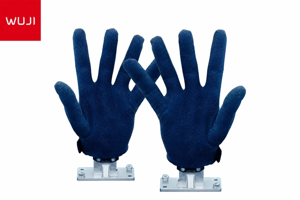
RC G1 Tasthalsklappen <unk> Datenprotokoll & Paarungsreferenz
Binärformat, AT-Befehlssatz, LED-State-Tabelle und Fehlerbehebung für die RC G1 Tactile Glove-Serie- / Bluetooth-Protokollen.
Verwenden Sie diese Seite, wenn Sie Ihren eigenen Leser schreiben oder die G1 in eine benutzerdefinierte Datenleitung integrieren. Sie umfasst das binäre Rahmenformat, den AT-Befehlszug auf dem Serienkanal, jeden LED-Zustand und die häufigsten Fehlermodi. Wenn Sie nur einplücken und aufnehmen müssen, beginnen Sie mit den [Windows]
Referenz Aktualisiert Mai 2026 Schwierigkeit: Weiterentwicklung
1. Hardware-Architektur
Ein G1-Einsatz hat fünf Komponenten. Nur die ersten vier sind für eine Einhandschuhe erforderlich; der USB-Hub ist für Multi-Handschuhe (LH + RH) -Setups.
- Warn Sensor-Array. 162 piezoresistive Sensorpunkte auf einer 16×16 logischen Matrix angeordnet (256 ADC-Slots, davon 162 sind physisch mit Sensoren verbunden; die unkabelten Slots werden in der Nähe von Null gelesen und können in Software verborgen werden).
- Daten-Akquisitionsmodul (A-Board). ESP32-basierte Bluetooth-MCU mit integrierter 300 mAh / 3,7 V-Batterie, USB-C für Ladung / Daten / Firmware, Hardware-Taktbutton und Status-LED. 50 × 32 × 15,5 mm; 6,6 g-Board + ~15 g-Batterie.
- Bluetooth-USB-Empfänger (Dongle). 1:1 mit einem einzigen A-Board gekoppelt. USB-A, 66.1 × 23.2 × 13 mm. Optional
Kabel-Nurbetrieb ist voll unterstützt. - USB 3.0-to-Type-C-Kabel (2 m). Serienverbindung bei 921 600 Bps Standard, optionales 3 000 000 Bps Hochgeschwindigkeitsmodus.
- USB-Schnittstelle. Für mehrhandschichtliche Anlagen (z. B. bi-manuale LH + RH).
Datenfluss:
  +--------------------+     +--------------------+        +--------+
  |  Fabric sensors    | --> |  A-board ADC       | --+--> | Host   |
  |  (162 / 16x16)     |     |  (ESP32 + IMU)     |   |    |        |
  +--------------------+     +--------------------+   |    +--------+
                                       |              |
                                       | BLE 30 Hz    | USB-C 100 Hz
                                       v              | (921600 / 3M)
                              +--------------------+  |
                              |  BT USB dongle     | -+
                              |  (CH340 endpoint)  |
                              +--------------------+
2. Serienkonfiguration
- Standard-Port-Einstellungen: 921 600 Baud, 8N1, keine Durchflusssteuerung.
- Optional Hochgeschwindigkeitsmodus: 3 000 000 Baud
erfordert eine firmware-seitige Konfigurationsänderung, Kontaktunterstützung. - USB-Chips sowohl am Datenübernahme-Modul (wenn sie über eine Kabelleitung verfügbar sind) als auch am Bluetooth-Dongle: CH340 (WCH USB ID
T4 ). - Linux: In-Tree-Kernel-Treiber
T5 . macOS: Installieren T6 . Windows: Installieren T7 .
Das gleiche in § 3 beschriebene binäre Protokoll funktioniert entweder auf dem kabelgebundenen oder dem BT-Dongle-Serieweg
3. Binärformat
Eine komplette Sensorlässigkeit wird als zwei Pakete geliefert, die zusammen 256 Druckwerte plus 16 Byte von IMU-Daten tragen. Jedes Paket beginnt mit dem konstanten 4-Byte-Synchronisierungshede
Byte layout for one sensor pair (packet 1 + packet 2)
| Offset | Length | Field | Description |
|---|---|---|---|
| Packet 1 (sequence = 0x01) — 134 bytes total | |||
0–3 |
4 B | Sync header | Constant AA 55 03 99 |
4 |
1 B | Sequence | 0x01 = first half |
5 |
1 B | Sensor type | 0x01 LH, 0x02 RH, 0x03 LF, 0x04 RF, 0x05 WB |
6–133 |
128 B | Pressure payload A | First 128 of 256 raw pressure values, 8-bit unsigned ADC (0–255) |
| Packet 2 (sequence = 0x02) — 150 bytes total | |||
0–3 |
4 B | Sync header | Constant AA 55 03 99 |
4 |
1 B | Sequence | 0x02 = second half |
5 |
1 B | Sensor type | Same value as packet 1 |
6–133 |
128 B | Pressure payload B | Last 128 of 256 raw pressure values |
134–149 |
16 B | IMU quaternion | 4 little-endian IEEE-754 floats: w, x, y, z |
Identifikationsnummern für Sensor-Typ
| ID | Code | Device class |
|---|---|---|
0x01 |
LH | Left Hand |
0x02 |
RH | Right Hand |
0x03 |
LF | Left Foot |
0x04 |
RF | Right Foot |
0x05 |
WB | Whole Body |
Bearbeitete Hex-Fang
Rohbyte aus einem Live-Linken-Gerät, das auf einem Schreibtisch sitzt (verknüpft für Lesbarkeit):
[14:04:29.427]  AA 55 03 99 01 01 00 00 00 00 00 00 00 00 00 00 ...  (128 B payload)
[14:04:29.428]  AA 55 03 99 02 01 00 00 ... 00 62 F3 00 00 00 ...      (144 B payload, last 16 B = IMU quaternion)
Referenzparser (Python)
Minimaler Parser, der die beiden Rohpakete nimmt und eine Sensor-ID, den 256-Zell-Druckvektor und das Quaternion zurückgibt.
import struct, numpy as np

def parse_pair(packet1: bytes, packet2: bytes):
    assert packet1[:4] == packet2[:4] == b"\xAA\x55\x03\x99"
    assert packet1[4] == 0x01 and packet2[4] == 0x02
    sensor_id = packet1[5]                              # same on both halves
    pressure = np.frombuffer(packet1[6:134] + packet2[6:134], dtype=np.uint8)  # 256 pts
    qw, qx, qy, qz = struct.unpack("<ffff", packet2[134:150])
    return sensor_id, pressure, (qw, qx, qy, qz)
Framing Tipp: auf einem lauten USB-Link, suchen Sie nach dem 4-Byte-Sync-Header, anstatt sich auf feste Offset-Verbindungen zu verlassen. Wenn Sie ein Sequenz-2-Paket ohne eine vorherige Sequenz-1 erhalten, lassen Sie es fallen und wieder synchronisieren
4. Karte der logischen Kanäle
Die 162 drahtgebundenen Sensorpunkte werden in einem 16×16-Gitter (256 Zellen, indexiert in der Reihe 1
Probenfrequenz: 100 Hz mit Kabel oder 30 Hz Bluetooth. Einpunkt-Dynamikbereich: 0
| 1 | 2 | 3 | 4 | 5 | 6 | 7 | 8 | 9 | 10 | 11 | 12 | 13 | 14 | 15 | 16 |
| 17 | 18 | 19 | 20 | 21 | 22 | 23 | 24 | 25 | 26 | 27 | 28 | 29 | 30 | 31 | 32 |
| 33 | 34 | 35 | 36 | 37 | 38 | 39 | 40 | 41 | 42 | 43 | 44 | 45 | 46 | 47 | 48 |
| 49 | 50 | 51 | 52 | 53 | 54 | 55 | 56 | 57 | 58 | 59 | 60 | 61 | 62 | 63 | 64 |
| 65 | 66 | 67 | 68 | 69 | 70 | 71 | 72 | 73 | 74 | 75 | 76 | 77 | 78 | 79 | 80 |
| 81 | 82 | 83 | 84 | 85 | 86 | 87 | 88 | 89 | 90 | 91 | 92 | 93 | 94 | 95 | 96 |
| 97 | 98 | 99 | 100 | 101 | 102 | 103 | 104 | 105 | 106 | 107 | 108 | 109 | 110 | 111 | 112 |
| 113 | 114 | 115 | 116 | 117 | 118 | 119 | 120 | 121 | 122 | 123 | 124 | 125 | 126 | 127 | 128 |
| 129 | 130 | 131 | 132 | 133 | 134 | 135 | 136 | 137 | 138 | 139 | 140 | 141 | 142 | 143 | 144 |
| 145 | 146 | 147 | 148 | 149 | 150 | 151 | 152 | 153 | 154 | 155 | 156 | 157 | 158 | 159 | 160 |
| 161 | 162 | 163 | 164 | 165 | 166 | 167 | 168 | 169 | 170 | 171 | 172 | 173 | 174 | 175 | 176 |
| 177 | 178 | 179 | 180 | 181 | 182 | 183 | 184 | 185 | 186 | 187 | 188 | 189 | 190 | 191 | 192 |
| 193 | 194 | 195 | 196 | 197 | 198 | 199 | 200 | 201 | 202 | 203 | 204 | 205 | 206 | 207 | 208 |
| 209 | 210 | 211 | 212 | 213 | 214 | 215 | 216 | 217 | 218 | 219 | 220 | 221 | 222 | 223 | 224 |
| 225 | 226 | 227 | 228 | 229 | 230 | 231 | 232 | 233 | 234 | 235 | 236 | 237 | 238 | 239 | 240 |
| 241 | 242 | 243 | 244 | 245 | 246 | 247 | 248 | 249 | 250 | 251 | 252 | 253 | 254 | 255 | 256 |
5. AT-Befehlssetzungen (Bluetooth-Paarmachung)
Senden Sie diese als ASCII-Streifen mit einer
| Command | Response | Purpose |
|---|---|---|
AT |
OK |
Sanity check the serial link. |
AT+SCAN=1 |
OK, then one +SCAN=<i>,<MAC>,<RSSI>,<adv-len>,<name_MAC> line per discovered device |
Start a BLE scan; look for lines containing JQ-LH, JQ-RH, JQ-LF, JQ-RF, or JQ-WB. |
AT+CONN=<MAC> |
OK, then binary sensor frames begin streaming |
Open a connection to the discovered MAC. Pairing is persistent across power cycles. |
AT+DISCONN |
OK |
Drop the current link. |
AT+VER |
firmware version string | For support reports. |
Arbeitsbeispiel
> AT+SCAN=1
< OK
< +SCAN=1, 8277169C745A, -1, 18, Redmi Watch 3 745A
< +SCAN=2, 3C8A1F2E9A36, -1, 23, JQ-RH_3C:8A:1F:2E:9A:36   ← the device we want
< +SCAN=3, 0,88F3079C11B4, -1,9, KeepB4-B4

> AT+CONN=3C8A1F2E9A361
< OK
< (binary sensor frames begin streaming ...)
** Identifikationsmerkmal:** die Präfix
6. LED-Staatsreferenz
Datenakquisitionsmodul Tastenfunktionen
| Action | Effect |
|---|---|
| Short press while in standby | Wake device and run IMU calibration. Red LED on briefly, then blue flashes while advertising. |
| Short press while operational | Trigger an IMU re-calibration. Keep the module flat and still for ~2 s. |
| Long press | Power off. Red LED on solid until the device is off. |
Modul für die Datenerfassung Status LED-Farbe
| Color | Meaning | Battery |
|---|---|---|
| Solid Blue | Bluetooth connected, high battery | > 3.3 V |
| Solid Green | Bluetooth connected, medium battery | 3.1 – 3.3 V |
| Solid Red | Bluetooth connected, low battery (charge soon) | ≤ 3.1 V |
| Red flashing | Bluetooth disconnected / advertising | — |
| Blue flashing | Pairing mode / advertising | — |
| Solid White | Charging via USB-C | — |
| LED off | Standby (auto-entered after 1 min of no pressure change — press button to wake) | — |
Bluetooth-Dongle LED
| State | Meaning |
|---|---|
| Red flashing | Not connected to any device. |
| Red + Blue both solid | Connected to a paired device. |
| Red solid only | Communication abnormal. Unplug and replug the dongle to recover. |
7. Neuausgleich (wenn ein Handschuh seinen Dongel verloren hat)
- Stromkreislauf des Moduls für die Datenerfassung: Langdruck bis Rot und Kurzdruck bis zur Werbung (blaues Blinken).
- Wenn der Bluetooth-Dongle rot blinkt, dann wird er gescannt.
- Öffnen Sie den seriellen Port des Hostes auf dem Dongle bei 921 600 Baud
verwenden Sie T57 , T58 , das SSCOM-Nutzprogramm, das auf dem USB-Laufwerk versendet wird, oder die Companion App. - Führen Sie
T59 aus. Kopieren Sie den MAC von der Zeile, die mit T60 / T61 / usw. endet. - Laufen Sie
T62 . T63 gefolgt von binären Rahmen bedeutet, dass Sie paar sind. Die Verbindung ist beständig Sie müssen nach zukünftigen Leistungszyklen nicht reparieren, es sei denn, Sie tauschen Module oder Dongles aus.
8. Fehlerbehebung von Schwindelblatt
| Symptom | Resolution |
|---|---|
| Module won’t power on | Battery flat. Charge for 10 min via USB-C (solid white LED), then retry the button. |
LED red-flashing forever after AT+CONN |
The MAC isn’t a G1 device (you copied the wrong line from AT+SCAN=1). Re-scan and look for JQ-LH/RH/LF/RF/WB. |
| Stream starts and stops every minute | 1-minute no-pressure standby has kicked in. Bend a finger to keep traffic flowing, or short-press the wake button. |
Quaternion = (NaN, NaN, NaN, NaN) |
IMU lost calibration. Lay the module flat on a still surface and short-press the button to re-calibrate (takes ~2 s). |
Pressure values all 255 |
Cable is reversed (TX/RX swapped) on a custom harness, or you’re reading at the wrong baud. Reset to 921 600. |
| Dongle LED solid red | Communication abnormal. Unplug and replug the dongle. |
| Companion App activation fails | Disable VPN / corporate proxy and retry. |
Spezifikations-Snapshot
| Sensing | |
| Sensing points per hand | 162 |
|---|---|
| Resolution | 4 × 6 mm |
| Sensing area | 179 × 145 mm (±3%) |
| Max single-point load | 350 N |
| Accuracy | 0.01 N |
| Wiederholgenauigkeit | ±8% |
| Response time | < 0.2 ms |
| Durability | 200 000 cycles @ 3 MPa (automotive-grade) |
| Physical | |
| Ingress rating | IP21 |
| Weight per glove | 35.4 g |
| Minimum fold radius | < 0.2 mm |
| Streaming | |
| Sample rate | 100 Hz wired / 30 Hz Bluetooth (customizable ≤ 600 Hz) |
| Baud rate | 921 600 (default); 3 000 000 high-speed |
| Power | |
| Operating voltage | 3.5 – 5.0 V |
| Operating current | 48 mA |
| Bluetooth battery life | 3.75 h active |
| Standby | 1 week |
| Environment | |
| Operating temperature | −20 °C to 60 °C (textile sensor) / −25 °C to 85 °C (PCB) |
| Operating humidity | < 90% RH, non-condensing |
| IMU | |
| Part | TDK InvenSense ICM-42688 |
| Gyroskop | 3-axis, ±2000 °/s |
| Beschleunigungsmesser | 3-axis, ±16 g |
| ADC | 16-bit |
| Interface | I²C up to 1 MHz / SPI 24 MHz / I3C 12.5 MHz |